While the levelling of use cases provides a valuable way of systematizing use cases from the perspective of end-users and stakeholders, there is also a need to use them as input to the software development process.
To this end, the Sea and Underwater use cases provide a good starting point as they provide a level of detail amenable to more formalized expression. The use cases at these levels are typically expressed in terms of a sequence of steps in the use case and these can then lead to the development of UML sequence diagrams that realize the use cases. The steps are mapped to the actions in the UML sequence diagrams. The actions can be performed by actors and systems involved in the interactions. Note that other behavioural notations could also be used, such as UML Activity diagrams.
The UML sequence diagrams in Figures 3.2.1-1 through 3.2.1-6 depict how Sea level use cases for the 21090 datatype support example can be realized. The purpose of these examples is to demonstrate the traceability provided by the approach and thus the sequence diagrams can be considered as initial solutions to realizing use cases. These sequence diagrams might need to be revisited and refined during the detailed design phases.
The sequence diagrams use UML notes (in blue text boxes) to informally depict traceability to technical services that support the corresponding actions performed by the system. For example, the proposed Find and Import SI services used in the Import Datatype use case are expressed as invocations of the associated UML messages. These technical services are to be provided by the system components to be designed and implemented. Examples of these components are described in section 3.2.2 - UML Components and the Services They Provide.
Import Datatypes
The Import Datatypes use case realization is depicted in Figure 3.2.1-1. The Information Modeller makes use of the UML tool component through which she accesses the 21090 datatype repository component. This component can implement the proposed Find and Import SI services from the SI periodic table.
Note that the diagram identifies some SI services that were not listed in the current SI periodic table, notably:
- Access to (any kind of) repository, requiring an ID parameter to identify the repository
- Open the UML tool (or Access to the tool), requiring authentication credentials (this name for the service was taken directly from the use case description).
These services might need to be considered for further development of the SI periodic table.

Figure 3.2.1-1 Import 21090 Datatypes Use Case Realization
Localize Datatypes
The Localize datatypes use case is depicted in Figure 3.2.1-2. The Information Modeller performed most of the activities using the UML tool.
The use case makes use of the Update SI service for updating the existing information model and 21090 datatypes.
We note that the narrative use case description is silent on where the localized data models are stored, so the diagram introduces the Information Model repository (as opposed to the Datatype repository), assuming that the Information Modeller will access this repository to perform localization of the existing information models. The meta-data repository could be also added as required.
Note that the access to the repository was modelled through asynchronous messages for illustration purposes only. An alternative is to model it using request response pattern.
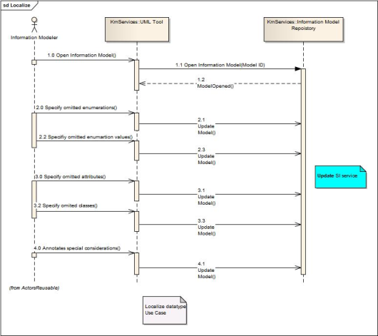
Figure 3.2.1-2 Localize 21090 Datatypes Use Case Realization
Generate XML mapping
The Generate XML mapping use case is depicted in Figure 3.2.1-3. This use case makes use of the Create SI service.
We note that the existing narrative use case description is silent on where the generated XML schema will be stored. It was assumed that this was stored in the Information Model Repository (rather than MetaData repository). Further, the use case realization might require some other services such as Generate Mapping Document but these were not modelled here.
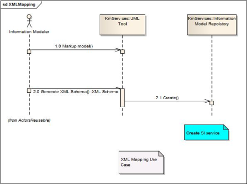
Figure 3.2.1-3 Generate XML Mapping Use Case Realization
Register datatype
The Register datatype use case realization is depicted in Figure 3.2.1-4. This use case makes us of the Find and Update SI services.
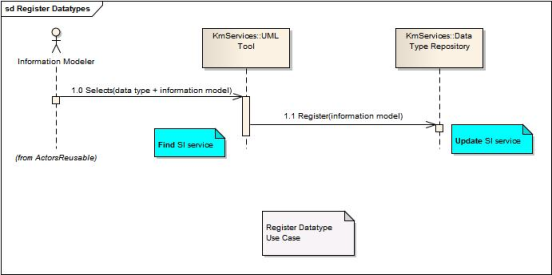
Figure 3.2.1-4 Register Datatypes Use Case Realization
Interoperate on Datatypes
The Interoperate on Datatypes use case is depicted in Figure 3.2.1-5. The use case makes use of the Validate SI service. The use case also identifies two other actors: the Software Engineer and System Architect.
Note that we also introduced a new component, referred to as the ECCF repository. This component stores the ECCF-related artifacts, such as interoperability scenarios. The ECCF repository provides the usual repository CRUD services, and the realization of this use case makes use of the read service.
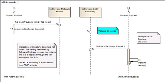
Figure 3.2.1-5 Interoperate on Datatypes Use Case Realization
Translation Service
The Translation Service use case realization is depicted in Figure 3.2.1-6. The use case makes use of the existing Register SI service and a new Access repository service. It was also assumed that the Translator toolset provides a number of SI services to support translation, such as Transform, Merge, Extend etc., as depicted in Figure 3.2.2-4 Translation Services.
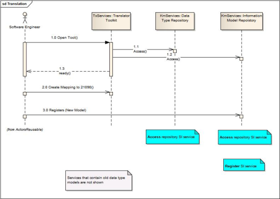
Figure 3.2.1-6 Translation Service Use Case Realization